grid coupling gap chart
Mechanical Power Transmission Systems TAPER GRID
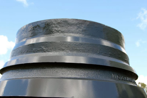
Coupling disassembly and grid removal. Parallel Misalignment Angular Misalignment Normal Gap COUPLING INDUSTRY | TAPER GRID COUPLING | 06 When disassembling the coupling, insert a screwdriver into the loop of the grid, alternating between the two sides of
Learn MoreGRID COUPLINGGRIDGRID COUPLINGCOUPLING - PowerDrive

Determine the required minimum coupling rating as shown below: MinimumCouplingRating=S.F. xTorque(lb-in) select the coupling T-10 Or T-20 which is suitable for yourapplication. Refer to
Learn MoreFalk Steelflex Grid Couplings - PDF Free Download
Grid Coupling Catalog Download the most up-to-date versions at Falk Steelflex Grid Selection is replacing a gear-type coupling with a 3 mm gap. 1.
Learn MoreGrid Coupling: Parts, Application & Specification | Linquip
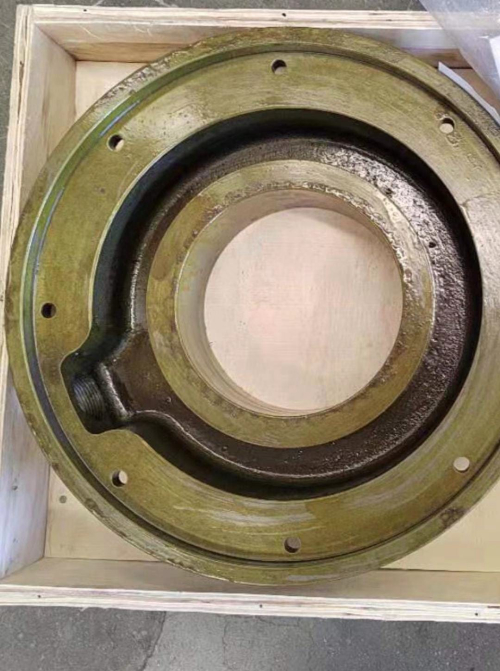
Aug 10, · Lubricating oil exists inside the cover, which lubricating the contact between the spring and the tooth surface in case of dry friction. The construction details of grid couplings are shown in the figure below. The numbers in the figure above indicate different components of a grid coupling that are as follows. 1.Seal ring. 2.Split cover. 3.Hub.
Learn MoreGrid - Lovejoy Inc
Chart on page GD-10 to determine the minimum size grid coupling Both the motor and compressor shaft are 3 inches long and the gap (BSE).
Learn MoreKOP-FLEX KOP-GRID Tapered Grid Couplings
Interchange Chart . KOP-GRID® tapered grid couplings are your best choice to protect your the coupling gap, each shaft must engage the hub by an.
Learn MoreDodge Couplings Catalog - Tecnica Industriale Srl
Grid element made from high strength steel that is quenched and tempered for long life. STYLE, SIZES AND RATINGS CHART. Coupling Styles. Number of Sizes.
Learn MorePDF 1000 Series GridPDF
Interchange Chart Vertical — Split Cover With readily available full assemblies and interchangeable components, Lovejoy's new line of grid couplings gives you the ability to avoid lengthy shutdowns. Our grid couplings combine high-torque, high-horsepower opera-tion with vibration, shock and misalignment capabilities not provided by other
Learn MoreGrid Couplings Grid Interchange Guide - Lovejoy Inc
line of grid couplings gives you the ability to avoid lengthy shutdowns. Our grid Grid Couplings. Interchange Chart. Lovejoy Gap. Length. Thru Bore.
Learn MoreTorque and Horsepower Ratings Service Factor Chart

Normal Gap 10% G Parallel P Angular X-Y Parallel P Angular X-Y 1020 0.006 0.002 0.012 0.010 0.118 Grid Couplings Interchange Chart Lovejoy Size Horizontal – Split Cover Vertical – Split
Learn MoreSelecting couplings for large loads - Machine Design
Within the metallic coupling types, gear couplings have the most misalignment capability, followed by disc and grid couplings. Shaft gaps. Grid
Learn MoreTorque and Horsepower Ratings Service Factor Chart Grid
Normal Gap 10% G Parallel P Angular X-Y Parallel P Angular X-Y 1020 0.006 0.002 0.012 0.010 0.118 Grid Couplings Interchange Chart Lovejoy Size Horizontal – Split Cover Vertical – Split Cover Lovejoy Torque . Grid Couplings Torque , action
Learn MoreTaper Grid Couplings
Check : Check speed (RPM), bore, gap and dimensions. KCP Tapered Grid Couplings are shaft-to-shaft couplings that shown in the diagram.
Learn MoreG-Flex Coupling - TB Wood's
General Guidance for the installation of TB Wood's grid couplings. General Guidance for the installation of Set gap using a spacer bar equal in thick-.
Learn MoreKop-Flex Kop-Grid Couplings - Regal Rexnord Corporation
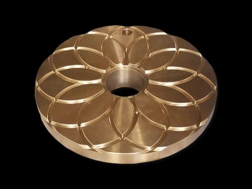
The KOP-GRID ® coupling, when under extreme loads, transmits the full load directly to driven equipment with the entire grid in full contact with the hub tapered teeth. The coupling is flexible within its rated capacity. The grid design functions as a resilient coupling by damping torsional vibration and cushioning shock loads.
Learn MoreGrid Configuration
Grid Configuration. This sample shows how to use scriptable grid options for an axis to control styling. In this case, the Y axis grid lines are colored based on their value. In addition, booleans are provided to toggle different parts of the X axis grid visibility. Randomize.
Learn MorePDF Grid Couplings - RINGSPANN CORPPDF
Interchange Chart For Grid Coupling RES ETO - vertically split cover Manufacturer RINGSPANN RES ETO Falk® Steelflex® Lovejoy® Grid Couplings Morse/Browning® Grid-Flex® Kop-Flex® Kop-Grid® Dodge® Grid-Lign® Size Max. Bore (inch) Torque (lb-in) RES 1020 ETO 1.12 425 1020T20 1.12 460 1020 1.12 460 GF2020V 1.12 422 1020V 1.12 422
Learn MoreInsert Chart - Atra-Flex Flexible Couplings
CORPORATE HEADQUARTERS ATR Sales Inc. 110 E. Garry Ave. Santa Ana, CA 92707 Tel: (800) 443-6613 Fax: (800) 988-9896
Learn MoreFalk Steelflex Grid Couplings - Rexnord
Falk® Steelflex® Grid Coupling Application Guide . Selection is replacing a gear-type coupling with a 0 .125" gap . 1 . Determine required rating:.
Learn MoreBlue-Flex Grid Couplings - Martin Sprocket
Step 6 .Check: Speed (RPM), bore, gap and dimensions . Example: A Field Engineer wants to use a Grid Coupling to connect a 60 horsepower electric motor running at 1750 RPM to a rotary lobe compressor . The shaft diameter of both the motor and compressor is 1 3/4" . Motor shaft extension is 3" and compressor shaft extension is 2 1/2" .
Learn MoreGrid Couplings - Drive Components
The 1020T, our smallest Grid Coupling, has a max bore of 1.125” and a torque rating of Use a spacer bar equal in thickness to the gap between shafts.
Learn MorePDF Blue-Flex Grid Couplings - Martin SprocketPDF
If torque is not given, calculate as shown below: Torque (lb-in) = HP x 63,000 RPM Where horsepower is the actual or transmitted power required by the application (if unknown, use the motor or turbine nameplate rating) and rpm is the actual speed the coupling is rotating .
Learn MoreGrid Spring Resilient coupling - Flexocon Engineers

TYPE A : AXIALLY SPLIT COVER. DIMENSIONS AND ENGINEERING DATA FOR GRID SPRING RESILIENT COUPLING: DIMENSIONS wt. in. Kg. Max. Pilot. A1. B. A. C. (Gap).
Learn MoreHow To Use This Manual Table of Contents TYPE
thru 140T10 Falk SteelfIex Tapered Grid Couplings. Unless otherwise stated, information for Sizes 1020T thru 1140T applies to Sizes 20T thru 140T respectively, e.g. 1020T = 2 — Gap and
Learn MorePDF GEAR COUPLINGGEAR COUPLING - PowerDrivePDF
From N-4 & N-5 to connect close coupled shafts (.250" gap) the double engagement Type 1025GC02 or Type 1025G20 coupling is theselection.:: Maximum speed capacity of 3,330 (1025GC02) and 5000 (1025G20) rpm exceeds required speed of 1170 rpm. Maximum bore capacity of 3.625" exceeds the actual shaft diameters and torque rating of
Learn MoreCoupling Tolerances vs. Shaft Alignment Tolerances, revisited
Jul 30, · The alignment of an 1800 RPM electric motor and centrifugal pump with a model 1070T grid coupling was checked. This was a fairly new installation with the initial alignment performed by the installation contractor. misalignment is 5.4 times the allowed shaft alignment tolerance of 0.7mils/1”. 3.8mils/1” is the same as a 15.2 mil gap at
Learn More
Leave a comment